ENGINEERING
Floating Wind Is a Mooring and Cable Problem Too
September and October 2026 floating-wind reports connect mooring integrity, dynamic cables and repair planning with the design of entire offshore arrays.
Research checked
Newest cited publication
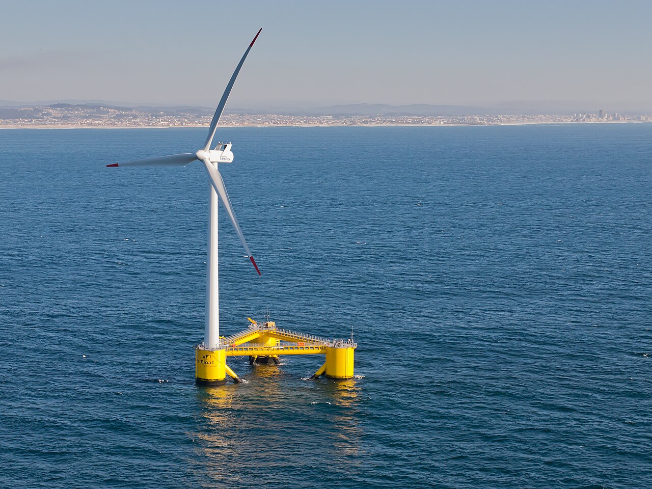
The WindFloat prototype off Portugal shows a floating turbine and semisubmersible foundation, providing physical context for the moorings and dynamic cables discussed here.
Untrakdrover / Wikimedia Commons · Image source · CC BY-SA 3.0

A floating wind farm is often pictured as a collection of turbines sitting on platforms. The less visible systems determine whether that picture can survive years at sea: mooring lines restrain each platform, anchors transfer forces into the seabed, and moving electrical cables carry its power. Two reports published by the Floating Offshore Wind Centre of Excellence in September and October 2026 bring these systems into sharper focus. They discuss integrity, replacement and installation risk, complementing recent reference designs for different United States sites. The emerging lesson is that station keeping, electrical export and marine operations must be designed as one connected engineering problem.
A reference design is tied to a particular sea
A 2025 Ocean Engineering paper by Lozon and colleagues developed mooring and dynamic-cable reference designs for a fifteen-megawatt semisubmersible turbine at three representative United States locations. The cases span water depths of 800 metres near Humboldt, 200 metres in the Gulf of Maine and 80 metres in the Gulf of Mexico. The selected systems differ accordingly: a taut polyester arrangement, a semitaut combination of chain and polyester, and a catenary chain arrangement. This is a useful reminder that one successful floating architecture does not establish a universal subsea design.
The basic mechanical choices have understandable consequences. A hanging chain can obtain much of its restoring behavior from lifting its own weight off the seabed. A taut line relies more directly on its axial response and geometry. Seabed footprint, vertical anchor load and how platform movement changes tension therefore differ. Water depth changes the space available for shaping both moorings and electrical cables. None of these observations selects a winner by itself. Site-specific waves, currents, soil conditions, installation access and acceptable platform motion determine which tradeoffs are relevant.
The power cable has to accommodate the platform’s movement
The reference-design study also developed lazy-wave dynamic cables matched to the mooring systems. Its workflow first used a quasi-static design tool and then time-domain dynamic simulations to examine relevant tension, fatigue and curvature limits. The paper reports designs meeting their specified checks. Those are model-based reference results, not a report that three full commercial arrays had been built and operated. Keeping that distinction visible makes the designs more useful: researchers can reproduce and vary a baseline without mistaking it for a universal installation prescription.
A cable is simultaneously an electrical component and a layered mechanical structure. Platform offset changes its shape; waves and currents add motion; local curvature changes strain in individual layers. A design can remain below a maximum tensile force yet accumulate unacceptable bending damage. Conversely, making a cable mechanically stiffer can move loads toward its attachment or neighboring sections. A simplified diagram is excellent for understanding the intended shape, but decisions require checking the actual material construction, buoyancy arrangement and termination behavior through the range of expected movements.
The September 2026 report treats repair as a design requirement
The Centre of Excellence’s September 3, 2026 monitoring and replacement publication uses a representative 900-megawatt North Sea case to examine mooring and cable integrity and operational constraints. Its public summary emphasizes that maintenance strategies must account for vessel availability, spare parts, weather and production downtime together. Its cost and duration estimates belong to the assumed case and scenarios; they should not be transferred directly into another project’s budget. The important transferable result is the structure of the decision, including the possibility that one failure reveals a wider integrity problem.
That last possibility changes the value of inspection. Finding one damaged line may indicate an isolated event, a shared manufacturing issue or a mismatch between the assumed environment and actual loading. Each explanation implies a different population at risk. A monitoring plan should therefore specify what observable change would trigger an inspection, a temporary operating restriction or a broader replacement campaign. Collecting data without such decisions can create an impressive dashboard while leaving the response to a deteriorating component undefined. Repair access should be investigated before the component becomes difficult to disconnect safely.
A reliable component can still be damaged during installation
The October 13, 2026 dynamic-cable installation publication extends earlier project work with stakeholder feedback and an installation risk assessment. Its public summary identifies recurring concerns around supply chains, vessels, interfaces, weather and operational coordination. This is an industry-informed risk study, not a randomized comparison proving one installation procedure superior. It is valuable because equipment qualification and offshore installation are frequently discussed separately even though handling can introduce the defect that later becomes an operational failure.
Consider a cable designed for an allowable bend radius. The relevant question is not only whether its final installed shape respects that limit. Engineers must examine every temporary configuration during transport, lifting, connection and recovery, including foreseeable delays. Likewise, a mooring line can meet its final tension requirement while its installation sequence creates an undesirable transient load. Interfaces deserve special attention because each contractor may understand its own equipment while making different assumptions about the neighboring operation. A joint sequence review exposes those assumptions before vessel time and weather pressure make changes expensive.
Sharing anchors changes the unit of analysis
The 2025 DeepFarm final-report record describes collaboration between Principle Power and NREL on innovative mooring and anchoring systems, including the possibility of sharing anchors among platforms. The work used computational tools to study floating-farm dynamics and costs for representative deep-water conditions. This is a design investigation, rather than evidence that every shared-anchor concept is ready for deployment. Its significance is that the farm, rather than the isolated turbine, becomes the object being optimized.
Sharing can reduce the number of some components while increasing dependence between neighboring machines. A load arriving from one platform may coincide with, oppose or combine unfavorably with another. A maintenance action on one connection can change the loads or operating constraints of others. The seabed foundation must be evaluated for these combined directions and histories, not merely for an average total force. These are reasons to investigate coupling explicitly, rather than assume that dividing an anchor’s cost among more turbines automatically divides risk by the same proportion.
What would make an array design convincing
A strong validation programme proceeds across scales without pretending that one scale contains every answer. Material and connector tests establish local properties. Basin experiments can examine coupled platform motion under controlled waves. Numerical models connect those observations to site conditions and longer histories. Field measurements then test whether the assumed loads, movements and degradation mechanisms persist in actual operation. Each stage should identify the configuration tested and the uncertainties it leaves unresolved, so later agreement can be interpreted rather than merely celebrated.
For a prospective array, the decisive evidence also includes damaged conditions. What happens after one mooring line becomes unavailable? Can a failed cable be isolated without losing an avoidable portion of production? Is a replacement operation feasible within credible weather and vessel constraints? The recent publications do not supply one complete answer for all sites, but they make the questions harder to overlook. Floating wind advances when its unseen connections become inspectable, repairable and predictable. Bigger arrays will require that system-level discipline at least as much as they require stronger individual components.
Sources & further reading
Primary papers, project documentation, and research releases used in this article. Publication dates below refer to the sources themselves.
- Mooring Line and Dynamic Cable Monitoring Replacement MethodologiesFloating Offshore Wind Centre of ExcellencePublished Checked
- Dynamic Cable Installation Risks and Failure MitigationFloating Offshore Wind Centre of ExcellencePublished Checked
- Reference Mooring and Dynamic Cable Designs for Representative U.S. Floating Wind Farms: Article No. 120473National Laboratory of the RockiesChecked
- Innovative Deep-Water Mooring Systems for Floating Wind Farms (DeepFarm): Cooperative Research and Development Final Report, CRADA Number CRD-20-16882National Laboratory of the RockiesChecked
FOLLOW THE QUESTION
Explore engineering