ENGINEERING
HVDC Expansion Depends on Hardware That Can Be Tested Together
InterOPERA’s 2026 updates show why the next generation of direct-current grids needs compatible controls, realistic models and shared validation procedures.
Research checked
Newest cited publication
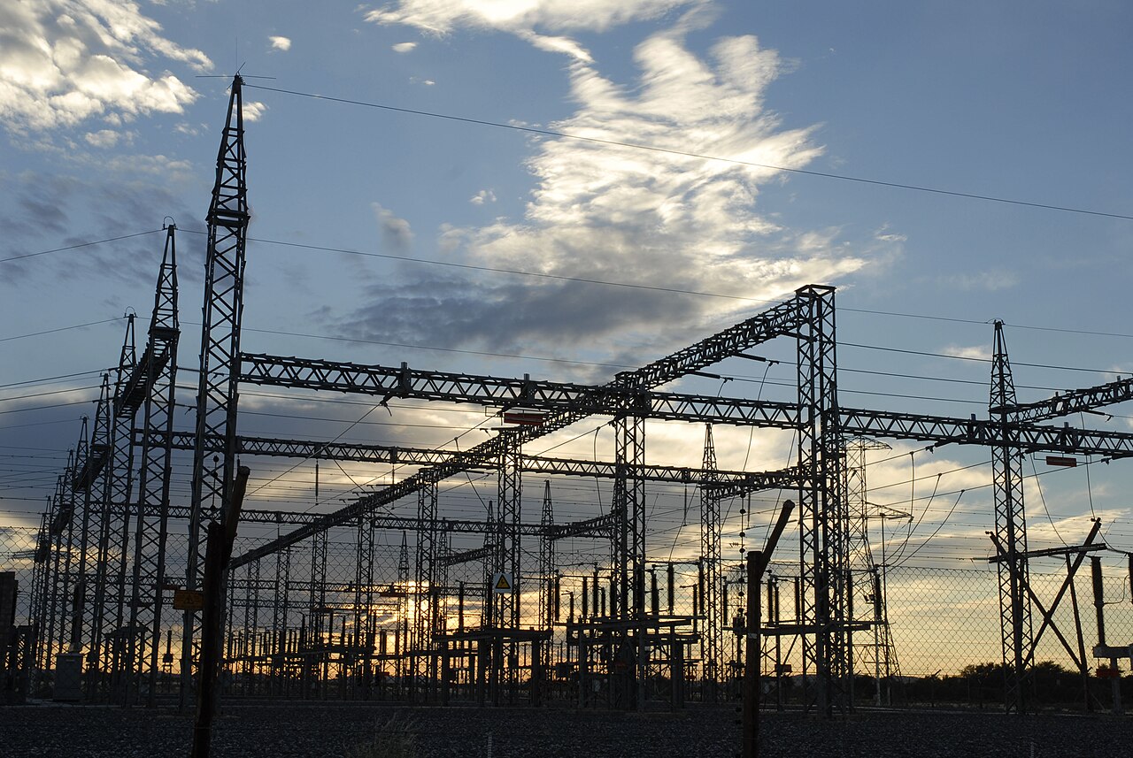
An archive substation photograph illustrates the complexity of grid hardware. It is background rather than a photograph of the HVDC interoperability tests discussed in the article.
Graeme Williams / Media Club · Image source · CC BY-SA 2.0

Building a larger electricity network is partly a matter of cables and converters, but connecting equipment from different suppliers adds a less visible challenge: making their fast control and protection systems cooperate. High-voltage direct current, or HVDC, is especially attractive for moving large amounts of offshore power over long cable routes. Its next step involves networks with more than two terminals and, potentially, more than one equipment vendor. InterOPERA’s 2026 publications and project updates describe the transition from shared specifications toward interaction studies and physical control replicas. They show progress on an important enabling technology while making clear that laboratory validation and operational deployment remain different milestones.
Why offshore transmission becomes a system problem
TenneT’s April 2025 explanation of its two-gigawatt offshore connection standard describes electricity collected from turbines, converted offshore to direct current and returned onshore to alternating current. Its cable system uses a 525-kilovolt arrangement and includes positive and negative poles, a neutral cable and optical fibre. This is a useful concrete architecture, rather than a claim that every future connection will use identical equipment. The fibre is a reminder that a power connection carries information as well as energy: monitoring, coordination and protection depend on communications and their failure behavior.
The familiar electrical tradeoff is that raising voltage allows the same power to move at lower current, reducing resistive heating for a given resistance. A simple illustrative conductor carrying 1,000 amperes through one ohm dissipates one megawatt; halving the current reduces that loss to a quarter of a megawatt. Those invented values explain the square-law relationship, not a real cable’s design. Actual selection also involves insulation, thermal conditions, converter costs, installation and operating constraints. A successful network therefore requires agreement on more than the nominal voltage printed on individual components.
Compatible connections need compatible behavior
Two converters can satisfy their individual performance requirements yet interact poorly once connected. Each reacts to a changing electrical environment, and its actions become part of the environment seen by the other. If both react too strongly at the same frequency, the combined system can oscillate. If their protective actions rely on incompatible assumptions, one disturbance can provoke unnecessary disconnection elsewhere. The word interoperability consequently describes behavior over time, including abnormal conditions, rather than only physical connector compatibility or agreement on a communications message format.
The European Commission’s InterOPERA reporting page, updated June 23, 2026, describes functional specifications, minimum simulation requirements and a staged validation process. It reports the start of control-cubicle and model deliveries and early dry runs finding conformity and interoperability gaps. That is a credible development-stage achievement: discovering a mismatch in a laboratory is precisely why the process exists. The report describes work performed through the end of 2025 and the transition into validation, so its update date should not be confused with the date of a completed commercial system.
A model and a control replica test different things
InterOPERA’s August 2026 publication summaries discuss minimum requirements for vendor models and physical control-and-protection replicas. They identify practical obstacles including incompatible software, different simulation time steps and numerical conflicts. This matters because an interaction study can fail for two very different reasons: the real controls may be incompatible, or the simulation arrangement may misrepresent them. Without a verified model interface, engineers risk tuning physical controls to compensate for an artifact of the test platform.
A software model makes it easier to inspect many operating cases and repeat a disturbance precisely. A physical control replica runs actual or representative control hardware against a simulated electrical plant, exposing timing and interface details that a simplified model can hide. Neither reproduces every property of a complete converter station. A convincing programme checks consistency between them, documents how measurement and communications delays enter the loop and explains which physical effects remain outside the representation. Passing one setup then becomes evidence with a defined scope, rather than a vague assertion that the entire technology has been proven.
Protection choices shape what survives a disturbance
A May 2025 preprint by Van Deyck and colleagues proposes a graph-based method for screening protection configurations in HVDC grids and electrical energy hubs. It compares how arrangements of breakers, lines and converters divide a system into protection zones and affect the impact of faults. The research is about selecting promising configurations for further analysis; it is not evidence that a particular breaker has passed a full-power interruption test. The distinction matters because network architecture and individual equipment capability answer related but separate engineering questions.
There is a useful general analogy to a building’s fire compartments. More boundaries can limit the spread of a disturbance but introduce cost, equipment and coordination requirements. In a power network, the relevant boundaries must act quickly enough and leave an acceptable portion of the system operating afterward. Their value depends on power-flow direction and the location and type of fault. A configuration that looks economical under one operating state may disconnect too much equipment under another. Screening many possibilities helps direct expensive detailed studies toward credible candidates, provided its simplifying assumptions remain explicit.
Transient stress links control choices to hardware ratings
InterOPERA’s 2026 publications also discuss insulation coordination and transient studies. The connection is physical: a control decision, converter blocking event or fault-clearing sequence changes currents and voltages seen by actual insulation and switching equipment. An average steady-state operating point does not reveal the highest transient stress. Designers must examine the relevant disturbances, the timing of protective actions and the assumptions about the rest of the network. Otherwise, each vendor could reasonably design for a different maximum electrical environment.
The practical implication is that hardware margins and control specifications should be developed together. Increasing one component rating may not solve a poorly damped interaction, while changing a control setting can shift stress elsewhere. A shared test case needs enough information to make those changes traceable without forcing vendors to disclose every proprietary implementation detail. Black-box models can help protect intellectual property, but their operating range and limitations have to be specified. Confidentiality is compatible with engineering assurance only when the agreed interface still permits meaningful challenge and independent checks.
What the current milestone means for future grids
Hitachi’s 2026 technology review describes InterOPERA’s first phase as completed in 2025 and the second phase as validation using software and physical demonstrators, with project completion scheduled for 2027. It reports delivering software-in-the-loop and hardware-in-the-loop control and protection systems to RTE and Delft University of Technology laboratories. These are tangible preparations for interoperability testing. They do not show that a fully interoperable multi-vendor offshore transmission grid is already in routine service, and the planned completion date remains a schedule rather than a measured outcome.
The next convincing evidence will be a transparent chain from functional requirement to test case, observed interaction and resolved issue. Independent replication should show that a remedy works across relevant configurations instead of merely calming one demonstration. Operators will also need procedures for introducing replacement equipment and software updates without invalidating previous assurance. HVDC expansion becomes easier when compatibility is something suppliers can demonstrate repeatedly. The 2026 work is important because it makes that demonstration more concrete, moving the discussion from a desirable future network toward the instruments, models and agreements needed to test one responsibly.
Sources & further reading
Primary papers, project documentation, and research releases used in this article. Publication dates below refer to the sources themselves.
- PublicationsInterOPERAChecked
- Enabling interoperability of multi-vendor HVDC gridsEuropean Commission CORDISChecked
- Hitachi Technology 2026 - Power GridsHitachiPublished Checked
- Aansluiten van een windpark met onze 2 gigawatt-standaardTenneTChecked
- Shortlisting Protection Configurations for HVDC Grids and Electrical Energy HubsarXivPublished Checked
FOLLOW THE QUESTION
Explore engineering